By Ben Richardson
Do you have a multitude of similar blocks that you store and use on a regular basis? If so, it is likely that you spend numerous hours finding, inserting, scaling, rotating and editing these blocks as part of your working routine. Maybe you have never thought of this as lost time, but did you know Dynamic Blocks can significantly reduce the time you spend tinkering with your block library and let you concentrate on more important things?
This may seem like breaking news to many AutoCAD users (advanced users included); however, one of AutoCAD’s best-kept secrets has actually been around for some time now. Dynamic Blocks were introduced as part of AutoCAD 2006. In contrast to standard blocks, Dynamic Blocks can take on a predefined level of intelligence, which allows you to very quickly change their visible appearance.
More specifically, you can stretch Dynamic Blocks to size without the tedious use of the Scale command, and you can alter Dynamic Block’s appearance by turning certain objects within your block on or off without having to use the explode command, all the while maintaining proportions, the correct size of fixed size objects and relative positions.
In this tutorial, we will cover:
- The potential use of Dynamic Blocks
- The possibilities available with the use of Dynamic Blocks
- How to author Dynamic Blocks using the Block Editor
- Potential problems you may encounter when authoring Dynamic Blocks
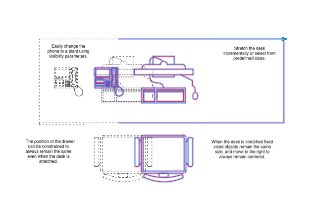
Let’s get started with an example of an office workstation. You can create a dynamic block that allows the length of a desk to be stretched, while at the same time maintaining the size and relative position of objects, such as chairs. You can also change certain elements, such as the type of computer sitting on the desk, replacing a telephone with a plant, moving a chair and so on.
Dynamic Blocks may be hard to get your head around at first; however, in their most complex form they are nothing more than a combination of two features: parameter(s) + action(s). By creating a parameter, you can then attach an action to it, thus making a Dynamic Block. This article will now guide you through the four steps necessary to making Dynamic Blocks.
Step One: Planning Your Dynamic Block
Before creating a Dynamic Block, first take some time to consider what you want to create. This may sound obvious, but if you’re looking to improve an existing block library, serious improvements can be made by simply thinking of ways to make full use of the Dynamic Block tool.
Remember that Dynamic Blocks are nothing more than parameter(s) + action(s). The table below should help get your creative juices flowing. It outlines what parameters are contained within AutoCAD, and which actions can be added to these parameters.
|
Parameter |
Available Action(s) | Uses |
| Point | Move, Stretch | Move, or Stretch by selecting a predefined point of an object |
| Linear | Move, Scale, Stretch, Array | Move, Scale, Stretch, or Array based on a linear distance |
| Polar | Move, Scale, Stretch, Polar Stretch, Array | Move, Scale, Stretch, Polar Stretch, or Array based on polar distance |
| XY | Move, Scale, Stretch, Array | Move, Scale, Stretch, or Array at specified XY location |
| Rotation | Rotate | Rotate to a predefined angle |
| Flip | Flip | Flip along an axis |
| Alignment | None | Align perpendicular or tangent to other objects |
| Visibility | None | Turn on or off the visibility of certain objects within a block |
| Base Point | None |
Define a base point of the Dynamic Block to make its use in drawing mode easier |
Table 1, Possible Parameter + Action combinations.
Step Two: Defining Your Dynamic Block
Now that you have an idea of how you want to use the Dynamic Block tool, you can begin defining your Dynamic Block.
Open the file that contains the objects you want to transform into a Dynamic Block. If your objects are already part of a block, make sure to use the Explode tool to break the block down to individual elements.
Note the explode tool is found within the Modify section of the Manage ribbon, or use command "EXPLODE."Select the objects you want to transform into a Dynamic Block.
With the objects selected, you now need to enter the Block Editor. Go to the Block Definition tab within the Insert ribbon or use command "BEDIT."
In the Edit Block Definition dialogue box, enter a suitable name for your block and click enter.
You have now entered the Block Editor and will have noticed the background color change, most likely to pale yellow or grey.
The Block Editor is a special window used for authoring Dynamic Blocks. The background changes remind you that you are no longer working in a drawing area and, as such, not all of AutoCAD's usual commands will work here.
To master Dynamic Blocks, you should familiarize yourself with the Block Authoring Palettes window.
By default, this should appear toward the left side of the screen when in Block Editor mode. If the Block Authoring Palettes window does not appear, go to the Block Editor ribbon and select Authoring Palettes from the Manage section.
Step Three: Adding Parameters
Once in the Block Editor, with the Block Authoring Palette window visible, you can begin adding a parameter.
To do this, select a parameter from the Parameters tab of the Block Authoring Palettes window.Note: These options will vary depending on the parameter selected, although all of the parameters offer fairly similar options. It is up to you if would like to add information to these options or continue creating the parameter as prompted. The following list should help you make that decision by describing each of the options.
- Name: Give a name to the parameter and this will appear in the properties palette when you select the parameter in the future. By default, an appropriate name will be assigned.
- Label: The label will be placed next to the parameter when you open your block in Block Editor mode. Change the label to suit your needs if the default label is not suitable.
- Chain: Used if you want trigger more than one change to a block. This can be set to Yes (Y) or No (N).
- Description: This description will display in the properties palette when you select a parameter in Block Editor mode.
- Base: Can be used to add a base point to the parameter.
- Palette: By default, parameter labels are displayed within the Properties palette when a Dynamic Block is selected in drawing mode. Enter No (N) to disable this feature.
- Value Set: By adding a value set, the parameter is limited to these values when the block reference is manipulated in drawing mode. Values can be constrained as increments (for example, a desk may be constrained to being sized to 100mm increments) or by a list (for example, only 1,500, 2,000 and 2,500).
In most cases, you will not need to enter this information and can follow the prompt to specify a start point.
Note: If you later decide that you want to enter a Name, Label, Chain, Description, Base, Palette or Value Set, you can find these options within the Properties palette of the parameter after it has been created. The Properties palette can be accessed using the “PROPERTIES” command.
Step Four: Attaching Actions
Not forgetting that Dynamic Blocks are, at their most complex level, a combination of parameter(s) + action(s), it is worth pointing out that three of the parameters contained within the block editor do not require an action to create a Dynamic Block, namely, the Alignment, Visibility and Base Point parameters (see Table 1).
For all of the six other parameters contained within the Block Editor we must attach an action to make things dynamic.
Firstly, go to the Actions tab of the Block Authoring Palettes windows and select as required from the actions available.
Note: Remember that an action must always be applied to a parameter. It cannot be directly applied to an object.
Next, do as prompted within the Command Line.
Note: Prompts will vary depending on the action and the parameter to which you are attaching the action.
If an action has been successfully attached to a parameter the previously observable exclamation mark (!) will have disappeared from the parameter.
If an exclamation mark remains this usually indicates the prompts have not been followed correctly, or the Parameter + Action combination is not possible. Another reason could be that too many grips have been applied to the parameter.
To reduce the number of grips, right click on the parameter and choose Grip Display.
Dynamic Blocks can be a powerful feature of AutoCAD. Following the upfront time spent on making a Dynamic Block, you could increase productivity, reduce the size of an existing block library and ensure your block is more accurate.
About the AuthorBen Richardson is a director of Acuity Training. Acuity Training is based in Guildford, UK and provides classroom-based IT training on packages including AutoCAD, Adobe and Microsoft Office. He’s a recent to convert to CAD but is an engineer at heart, having studied materials science at Cambridge University, UK.