Filleting Polylines
If a geometry is made with a polyline and has several vertices, then a fillet can be applied with a uniform radius value on all of these vertices with a single command. Let’s take, for example, the pentagon in Figure 1, which is made with AutoCAD’s polygon command using an inscribed circle of a radius of five units. The object type is polyline for this pentagon.
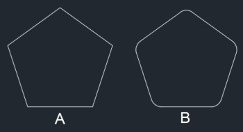

Figure 2. Polyline option in a fillet.
You will notice that a fillet will be applied on all vertices with radius of one unit.
Making Smooth Polyline Curves
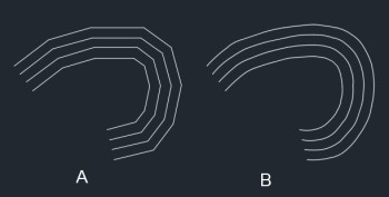
Let’s take the example of this contour diagram in Figure 3. In this image, you can see that the contour is made with a polyline, but it has sharp edges at the points where the vertices of this geometry lie. But in order to have a clear contour, we need to insure a smooth polyline at the vertices.
Converting Objects to Polylines
You can convert lines, arcs or even splines to a polyline curve using the Polyline Edit command. Let’s assume that we have an arc that we want to convert into a polyline; for that, type “PE” on the command line and press “Enter.” This will start the Polyline Edit command. Now click on the arc from the drawing area. Since the arc is not a polyline object, you will see this message on the command line (Figure 4).

Type “Y” on the command line, and press “Enter” to turn the arc into a polyline.
Creating a Polyline Spline Curve
By using this feature, you can create more controlled and smooth polyline spline curves from polyline curves. A polyline spline curve is not a mathematically accurate spline; rather, it is an approximate true spline curve. The curve behaves like a spline geometrically and it does not pass through the vertex points.
This curve can be used at places where you don’t want the accuracy of a true spline and you also want to retain properties of a polyline curve. The geometry of polyline spline curves can be modified using their control vertices, and you can also modify their properties using the Polyline Edit command.
To convert a simple polyline curve into a polyline spline, type “PE” on the command line, press “Enter,” click on polyline curve and select “Spline” from the options in the command line as shown in Figure 5.
Figure 5. Spline option in the Polyline Edit command.
Press “Enter” to exit the command. The polyline curve will be converted into a true spline curve.
Making a True Spline Curve from a Polyline
In the previous tip, we learned about converting a polyline curve into a polyline spline curve that geometrically looks like a spline but inherits properties of a polyline. You can convert this polyline spline into a true spline by using the Spline Edit command on a polyline spline.
Type “SPE,” press “Enter” then click on “Polyline Spline Curve” from the drawing area and press “Enter” again. The curve will now be converted into a true spline curve, and you can modify it using the Spline Edit command. You can also convert this spline into Spline with Fit points or spline with Control Vertices by modifying it from spline grip (Figure 6).
Figure 6. Spline Fit and Control Vertices options.
Adding Width to Polylines
In order to highlight polylines, you can add width to it. By adding width you can also ensure a fixed thickness of polyline which changes when overall scale of geometry is changed. The width of a polyline can also be varied between its vertices.
To apply width to an existing polyline, type “PE” on the command line and press “Enter.” Then select the polyline for which you want to change the width. Select the width option from the command line and enter the value of the width you want to apply on this polyline. Then press “Enter” twice to apply the change and exit the command.
In order to change the width of the polyline between its vertices, you can use the polyline command. Start the polyline command from the Draw panel of the Home tab or use its command equivalent—“PL”—and click at a point to create its first point. Now from the command line, select the width option, specify the starting width of the polyline and press “Enter.” I am selecting a value of one unit for the starting width. Now the command line will prompt you to specify the end width of the polyline. I am assigning the end width as zero units. Then press “Enter” again. Now specify the length of the polyline. Here I am assigning a length of 1.5 units. Finally, this is the polyline that I obtained using the above-mentioned settings—it looks like an arrowhead (Figure 7).
Figure 7. Polyline with varying width.
Adding Thickness to Polylines
Thickness is the geometrical property of a polyline that can be added to give it a 3D appearance. In order to add thickness to an existing polyline, select it from the drawing area and right-click and select Properties to invoke the Properties palette. From the General tab of the Properties palette, change the value of the thickness to the desired value. In this example, I am applying thickness to the polyline created in the example above, as well as to a polyline containing a uniform width of 0.2 units and another polyline with no width. In all of these cases, I am changing the value of the thickness to one unit.
Once the thickness value is applied, change the view to isometric (SW Isometric preferably) using ViewCube or View Controls. Also, change the visual style to shaded in order to see the change more clearly. This is the final geometry I obtained by applying all the changes mentioned above; although it may look like these are 3D geometries, they are actually 2D polyline curves (Figure 8).
Figure 8. Polylines with thickness.
Reversing Direction of Polylines
Reversing the direction of a polyline can be really useful if you are using a line type containing text; for example, if you are using a line type to show a gas pipeline, then there may be instances where the GAS letter may look upside down or reversed in the polyline (Figure 9). This polyline can be properly aligned by reversing its direction.
To reverse the direction of a polyline, double-click on it to activate the Polyline Edit command and select “Reverse” from the command line. You can also use its command equivalent, REVERSE.
If you try to reverse the direction of a polyline made with varying widths at its end points, you may not see any visible reversal of direction because the REVERSE command will only reverse the order in which the segment is created. In order to reverse the direction of polyline, you need to change the PLINEREVERSEWIDTHS system variable to 1.
Let’s try this on the polyline arrowhead created in example above. Type “PLINEREVERSEWIDTHS,” press “Enter,” type “1” as its value and press “Enter” again. Now type “REVERSE” on the command line, press “Enter,” select “Polyline” and press “Enter” again. You will notice that the direction of the polyline will also be reversed along with its order.
Conclusion
These methods of modifying polylines and their applications can be used in a variety of scenarios for making your drawings more informative using less geometries. If you have any questions related to this article, let me know in the comments below.
About the author
Jaiprakash Pandey is a corporate CAD trainer and designer currently working with the consulting engineering group Ramboll. He is an AutoCAD-certified professional as well as an Autodesk Expert Elite member and a mechanical engineer. Pandey also develops video courses for many online tutoring platforms and occasionally writes for AUGIWorld Magazine. You can reach him on his blog,
SourceCAD.