As the Autodesk updates roll out, the CAD company has just announced its August updates to its one-stop CAD shop, Fusion 360. The latest version adds electronics CAD (ECAD) and expanded browser client access.
Fusion 360’s updates underscore Autodesk’s vision of an all-inclusive software tool—a fusion of multiple disciplines all working in a single environment—that is needed in design and manufacturing. Whereas Fusion 360 may previously have covered purely mechanical design and manufacturing, the addition of ECAD acknowledges that modern products often have both mechanical and electrical parts. This means that users will ideally be able to move from sketching and modeling parts—including printed circuit board design, with various manufacturing processes in mind—to the actual production stage, either with drawings and tables or right to the CNC machines.
To learn more about the CAD software’s updates, ENGINEERING.com sat down with Autodesk’s Senior Product Manager Daniel Graham, who provided us with a demo of the software’s various features.
Sheet Metal Comes to Fusion 360
Fusion 360 now includes sheet metal design and manufacturing, considerably broadening its CAM capabilities. Although previously available only to specific beta testers, sheet metal is now available to all Fusion 360 users.
Graham explained that, by allowing private access to sheet metal, Autodesk was able to get feedback for the tool and then make improvements to it before the software’s public release. At the same time, some users were already able to begin leveraging the capability in their actual manufacturing process.
Fusion 360’s sheet metal application adds features that help the program catch up to existing sheet metal design software applications from other CAD vendors.
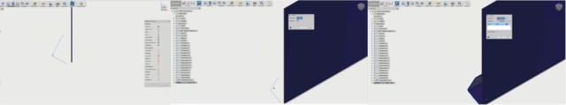
Fusion360 users can take a base flange, select multiple edges, draw out the length of the part and change the angle associated with the flange. That same tool can be used to create a contour flange from a sketch contour by dragging the edge and connecting it to an adjacent edge. With a miter flange, multiple edges can be picked and gaps and reliefs will be applied automatically.
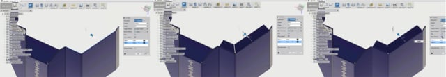
The sheet metal application also offers a unique approach to moving from folded to unfolded geometries. Within the modeling workflow, it’s possible to easily transition from folded to unfolded geometry and perform cuts or other changes. Once performed in either state, the change is made to the geometry in both its folded and unfolded forms.
One important aspect for manufacturing sheet metal is having an accurate flat pattern model. With Fusion 360, you have a clear lineage from 3D bent to a flat pattern and can go directly into CAM, rather than relying on manually outputting DXF or DWG data file. This greatly reduces the possibility of costly manufacturing errors. In Fusion 360’s CAM workspace, the sheet metals flat pattern can be leveraged directly to create a setup for water, laser, or plasma cutting.
When the geometry is sent for water or laser cutting, for instance, the manufacturing team can just pull up the flat pattern from the original geometry. Manufacturing details, such as a bend table, can also be added to the file so that, if a geometry has a bend, for example, the angle associated with the bend will populate the table.
Within Fusion 360, there is also a library of bend rules that can be shared and reused across an organization. Rules can be created to specify the bend radius, the K-factor, miter, rip, seam gap, bend conditions, corner conditions and other details that should be applied to a geometry. Bends can be defined as function of thickness either in the rule or override per bend.
Graham pointed out that this is just the beginning for sheet metal in Fusion 360. While the software can’t currently perform nesting operations, it is planned for a future update.
Mechanical Meets Electrical
Just as adding CAM to CAD in Fusion360 unites design and manufacturing, adding ECAD to Fusion 360 adds more versatility.
Through the acquisition of CadSoft last year, Autodesk became the proud owner of Eagle, the printed circuit board (PCB) design software that has been popular among engineers, hobbyists and students for the past 30 years. While there are still separate programs, Autodesk has since connected Eagle to its Fusion 360 workflow—the first Eagle integration for the software company—in the hopes of more closely integrating electrical and mechanical design.
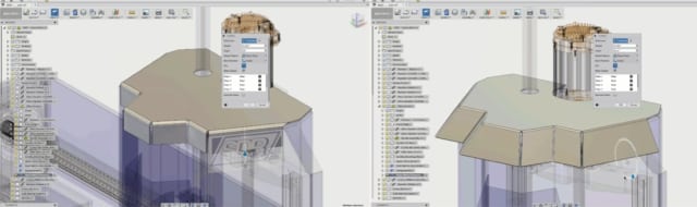
Graham demonstrated the possibilities with a Fusion 360 design of a radio with designed-in pocket for a PCB. Within Fusion 360, it’s possible to identify a portion of the design as a profile that will contain a PCB. Once that’s been performed, the profile shape can be pulled into Eagle and the electronic components can be placed onto the shape.
Populated with components, the PCB can then be pushed to Fusion 360, where the designer can then ensure that the board fits the mechanical design properly, determining if there are any interference between the electrical and mechanical designs.
If there are, the PCB can be modified inside of Fusion 360. Electronic components can be shifted, and the shape of the PCB can be modified to properly fit into the mechanical design. These changes can then be pushed to Eagle, where the PCB will be updated to reflect the modifications.
Necessary to this connectivity is a component library system that is shared by the MCAD and ECAD tools, as well as a design link system that connects the Eagle PCB to Fusion 360’s PCB feature. In addition to the bidirectional workflow between the two programs, this also gives electrical engineers the geometric flexibility found in a more robust 3D modeling tool like Fusion, as opposed to the 2D sketching found in Eagle.
Matt Berggren, director of Autodesk EAGLE, said of this new functionality, “Coupling electronics design with the mechanical CAD & manufacturing capabilities of Fusion 360 establishes Autodesk’s role in the end to end development of electronic products. In this latest version, individuals and even teams embedding electrical intelligence in their designs will be able to seamlessly share data between the electrical and mechanical engineers, collaborate on designs, iterate on electromechanical features like the shape of the PCB or the position of connectors, and produce complete downstream manufacturing data.”
Browser Client Access
The third large update to the software is expanded browser client access. Graham explained that Fusion users may want to access designs regardless of what computer hardware is sitting in front of them. For this reason, Autodesk augmented its existing Mac and Windows platforms with web browser access that includes authoring capabilities.
Naturally, modifying a file over the web isn’t going to be as powerful as doing so on the desktop, but it is possible to perform some operations through the browser. Specifically, sketching and parametric modeling can be performed online, and there is complete fidelity between the desktop and browser.
General Updates
In addition to the big three updates mentioned above, Autodesk also introduced a number of smaller updates. These include the following:
- The ability to cache a project for offline use
- The ability to share a library of models across an organization
- The ability to share and reuse a library of designs across an organization
- A streamlined method for creating arc slots
- Tangent dimensioning between sketches, and not just centers
- Improvements to lofting, including the ability to define whether a lofted feature is tangent to or a continuous part of an adjacent feature
- Greater control over sweeps
- Improved 2D drawing, including the ability to do group stretching of multiple dimensions; create dimension breaks; and reassociate dimensions after design changes